Click here to return to HAM Radio projects mainpage
PICBeacon - LF (and not only...) CW/QRSS beacon
This simple beacon is born after discussing with Giulio, ik2ded, on some ideas for LF. But it can be used also on VHF/UHF/SHF because it can send normal CW, QRSS or both.
You have two messages that you can send with different speeds in six different phases: in each phase you can set which message to send, the number of repeats and the outputs (relays) configuration.
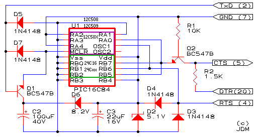
The heart of the system is the cheap and powerful microcontroller PIC16F84, by Microchip, with only few other components. You can see from the schematic that it is very simple!
![]()
The "TRIGGER" input is used as start trigger, if you want that the beacon freerun indefinitely, you can put a shorting jumper on this input.
The "KEYING" is the CW output for keying the TX
"OUT1, OUT2 and OUT3" are general purpose outputs with relay dry contacts for some things like change the power, switch the antennas, change the frequency, etc.
All the data (messages, speed, delays, repeats and relays drivings) are stored in the PIC EEPROM and this is the mapping:
From address 0000 to 001D: message #1, if you use less than 30 characters, you must fill the unused bytes with 00
From address 001E to 0031: message #2, if you use less than 20 characters, you must fill the unused bytes with 00
Address 0032: speed of message #1, a value from 00 to 7F (0 to 127) is the speed in wpm, from 80 to FF (128 to 255) means the duration in seconds of dot for QRSS with 128 added, for example, 83 (131) means QRSS with 3 seconds dot
Address 0033: speed of message #2 (same syntax of location 0032)
Address 0034: phase #1 configuration
| bit 7 (80) | bit 6 (40) | bit 5 (20) | bit 4 (10) | bit 3 (08) bit 2 (04) bit 1 (02) bit 0 (01) |
| 0 = message 1
1 = message 2 |
0 = out3 off
1 = out3 on |
0 = out2 off
1 = out2 on |
0 = out1 off
1 = out2 on |
number of repeats of the message from 00 to 07 (0 to 7), 0 means phase not active |
Address 0035: phase #2 configuration (same syntax of 0034)
Address 0036: phase #3 configuration (same syntax of 0034)
Address 0037: phase #4 configuration (same syntax of 0034)
Address 0038: phase #5 configuration (same syntax of 0034)
Address 0039: phase #6 configuration (same syntax of 0034)
Address 003A: delay in seconds after sending the message in phase #1, from 00 to FF (0 to 255) seconds
Address 003B: delay in seconds after sending the message in phase #2, from 00 to FF (0 to 255) seconds
Address 003C: delay in seconds after sending the message in phase #3, from 00 to FF (0 to 255) seconds
Address 003D: delay in seconds after sending the message in phase #4, from 00 to FF (0 to 255) seconds
Address 003E: delay in seconds after sending the message in phase #5, from 00 to FF (0 to 255) seconds
Address 003F: delay in seconds after sending the message in phase #6, from 00 to FF (0 to 255) seconds
With all the data in EEPROM, you need only to edit this memory directly on the programming software, I use ICProg (http://www.ic-prog.com/index1.htm) with a LudiPipo or JDM programmer (http://www.ic-prog.com/jdmprog.gif), without any needs to change the program. This is a sample of configuration.
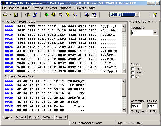
The message #1 is "IK2DED/B LF BEACON JN55IO " (note the four spaces at the end as 12+4 dashes delay) and it is long 39 characters, the 30th character is NUL (00)
The message #2 is "IK2DED/B JN55IO " (note the three spaces at the end as 9+3 dashes delay) and it is long 18 characters, the 19th and 20th characters are NUL (00)
The speed of message #1 is 10 wpm (value is 0A) and the speed of message #2 is QRSS with 3 seconds dot (value is 83)
In the phase #1 (value is 03), the message #1 will be sent (bit7=0), the three relays will be off (bit6=0, bit5=0 and bit4=0) and the message will be repeated three times (bit3-0=3)
In the phase #2 (value is 81), the message #2 will be sent (bit7=1), the three relays will be off (bit6=0, bit5=0 and bit4=0) and the message will be sent only one time (bit3-0=1)
In the phase #3 (value is 91), the message #2 will be sent (bit7=1), the relay 1 will be on (bit6=0, bit5=0 and bit4=1) and the message will be sent only one time (bit3-0=1)
In the phase #4 (value is A1), the message #2 will be sent (bit7=1), the relay 2 will be on (bit6=0, bit5=1 and bit4=0) and the message will be sent only one time (bit3-0=1)
The phase #5 and #6 are not used (value is 00)
The delay after phase #1 is 4 seconds (value is 04), after phase #2, 3 and 4 is 1 second (value is 01)
The program with an EEPROM contents sample is lfbeacon.zip and a better quality schematic is lfbeacon.pdf
Ciao and good work
Guido, ik2bcp / iu2r / ab9dg
Any question and/or comment to ik2bcp AT hamlan.org