Click here to return to HAM Radio projects mainpage
PICBeacon2 - CW/QRSS/DFCW beacon
This is an updated version of the beacon with some hardware additions (mainly leds) and DFCW.
You have two messages that you can send with different speeds in five different phases: in each phase you can set which message to send, the speed, the number of the repetitions and the outputs (relays) configuration.
The heart of the system is the cheap and powerful microcontroller PIC16F84/16F84A/16LF84A, by Microchip.
![]()
"TRIGGER" input is used as start trigger, if you want that the beacon runs indefinitely, you can put a shorting jumper on this input.
"KEYING" is the CW output for keying the TX.
"DFCW" is the FSK output for DFCW.
"OUT1/PTT" is an output mainly used for PTT but also for general purpose output.
"OUT2 and OUT3" are general purpose outputs with relay dry contacts for some things like: change the power, switch the antennas, change the frequency, etc.
Dip switches selects these settings:
| DIP 1 | DIP 2 | DIP 3 | DIP 4 | |
| OFF | OFF | OFF | OFF | All phases will be scanned and executed if active |
| ON | OFF | OFF | OFF | Only phase #1 is executed if active |
| OFF | ON | OFF | OFF | Only phase #2 is executed if active |
| ON | ON | OFF | OFF | Only phase #3 is executed if active |
| OFF | OFF | ON | OFF | Only phase #4 is executed if active |
| ON | OFF | ON | OFF | Only phase #5 is executed if active |
The data (messages, speed, delays, repeats and relays outputs) are stored in the PIC EEPROM and this is the mapping:
From addr. 0000h to 001Fh: msg #1 (max 32 chars), if you use less than 32 chars, you must fill the unused bytes with 00
From addr. 0020h to 002Fh: msg #2 (max 16 chars), if you use less than 16 chars, you must fill the unused bytes with 00
Address 0030h: phase #1 configuration
| bit 7 (80h) | bit 6 (40h) | bit 5 (20h) | bit 4 (10h) | bit 3 (08h) bit 2 (04h) bit 1 (02h) bit 0 (01h) |
| 0 = message 1
1 = message 2 |
0 = out3 off
1 = out3 on |
0 = out2 off
1 = out2 on |
0 = out1/ptt off
1 = out1/ptt on |
number of repeats of the message from 00h to 0Fh (0 to 15), 0 means phase not active |
Address 0031h: phase #2 configuration (same syntax of 0030h)
Address 0032h: phase #3 configuration (same syntax of 0030h)
Address 0033h: phase #4 configuration (same syntax of 0030h)
Address 0034h: phase #5 configuration (same syntax of 0030h)
Address 0035h: speed of phase #1
- value from 00h to 3Fh (0 to 63) is the speed from 1 to 64 wpm in CW
- value from 40h to 7Fh (64 to 127) means the duration in seconds of dot for QRSS with 3Fh added, for example, 42h (66) means QRSS with 3 seconds dot
- value from 80h to BFh (128 to 191) means the duration in seconds of dot/dash for DFCW mode 1 (see the note) with 7Fh added, for example, 82h (130) means DFCW mode 1 with 3 seconds dot
- value from C0h to FFh (192 to 255) means the duration in seconds of dot/dash for DFCW mode 2 (see the note) with BFh added, for example, C0h (192) means DFCW mode 2 with 1 seconds dot
Note: with DFCW mode 1, a pause of 1/4 of dot/dash time is added before the "keying", with DFCW mode 2, a pause of 1/2 of dot/dash is added before the "keying". For example, if the speed is C2h, the DFCW output is set to dot or dash, after 1.5s, the KEYING will be active and, after 3s, the KEYING will be not active and the DFCW output set to dot or dash.
Address 0036h: speed of phase #2 (same syntax of location 0035h)
Address 0037h: speed of phase #3 (same syntax of location 0035h)
Address 0038h: speed of phase #4 (same syntax of location 0035h)
Address 0039h: speed of phase #5 (same syntax of location 0035h)
Address 003Ah: delay in seconds after sending the message in phase #1, from 00h to FFh (0 to 255) seconds
Address 003Bh: delay in seconds after sending the message in phase #2, from 00h to FFh (0 to 255) seconds
Address 003Ch: delay in seconds after sending the message in phase #3, from 00h to FFh (0 to 255) seconds
Address 003Dh: delay in seconds after sending the message in phase #4, from 00h to FFh (0 to 255) seconds
Address 003Eh: delay in seconds after sending the message in phase #5, from 00h to FFh (0 to 255) seconds
Address 003Fh: not used
With all the data in EEPROM, you need only to edit this memory directly on the programming software, I use ICProg (http://www.ic-prog.com/index1.htm) with a LudiPipo or JDM programmer (http://www.ic-prog.com/jdmprog.gif), without any needs to change the program. This is a sample of configuration.
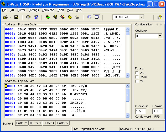
The message #1 is "IK2BCP/B IK2BCP/B JN55CM " (note the space at the end) and it is 25 characters long, the last 7 characters are NUL (00h)
The message #2 is "IK2BCP " (note the space at the end) and it is 7 characters long, the last 8 characters are NUL (00h)
In phase #1 (value is 11h), the message #1 will be sent (bit7=0), the OUT1/PTT relay will be on (bit6=0, bit5=0 and bit4=1) and the message will be repeated one time (bit3-0=1)
In phase #2 (value is B1h), the message #2 will be sent (bit7=1), the OUT1/PTT and OUT2 relais will be on (bit6=0, bit5=1 and bit4=1) and the message will be sent only one time (bit3-0=1)
In phase #3 (value is 11h), the message #1 will be sent (bit7=0), the OUT1/PTT relay will be on (bit6=0, bit5=0 and bit4=1) and the message will be repeated one time (bit3-0=1)
In phase #4 (value is D1h), the message #2 will be sent (bit7=1), the OUT1/PTT and OUT3 relais will be on (bit6=1, bit5=0 and bit4=1) and the message will be sent only one time (bit3-0=1)
In phase #5 (value is D1h), the message #2 will be sent (bit7=1), the OUT1/PTT and OUT3 relais will be on (bit6=1, bit5=0 and bit4=1) and the message will be sent only one time (bit3-0=1)
The speed of phase #1 is 10 wpm on standard CW (value is 09h)
The speed of phase #2 is QRSS3 (value is 42h)
The speed of phase #3 is 10 wpm on standard CW (value is 09h)
The speed of phase #4 is DFCW3 with 0.75s pause (value is 82h)
The speed of phase #5 is DFCW3 with 1.5s pause (value is C2h)
The delay after phase #1 is 4 seconds (value is 00h)
The delay after phase #2 is 0 seconds (value is 00h)
The delay after phase #3 is 4 seconds (value is 00h)
The delay after phase #4 is 0 seconds (value is 00h)
The delay after phase #5 is 0 seconds (value is 00h)
The program with an EEPROM contents sample is picbeacon2.zip and a better quality schematic is picbeacon2.pdf
Ciao and good work
Guido, ik2bcp / iu2r / ab9dg
Any question and/or comment to ik2bcp AT hamlan.org